Cavity Fill
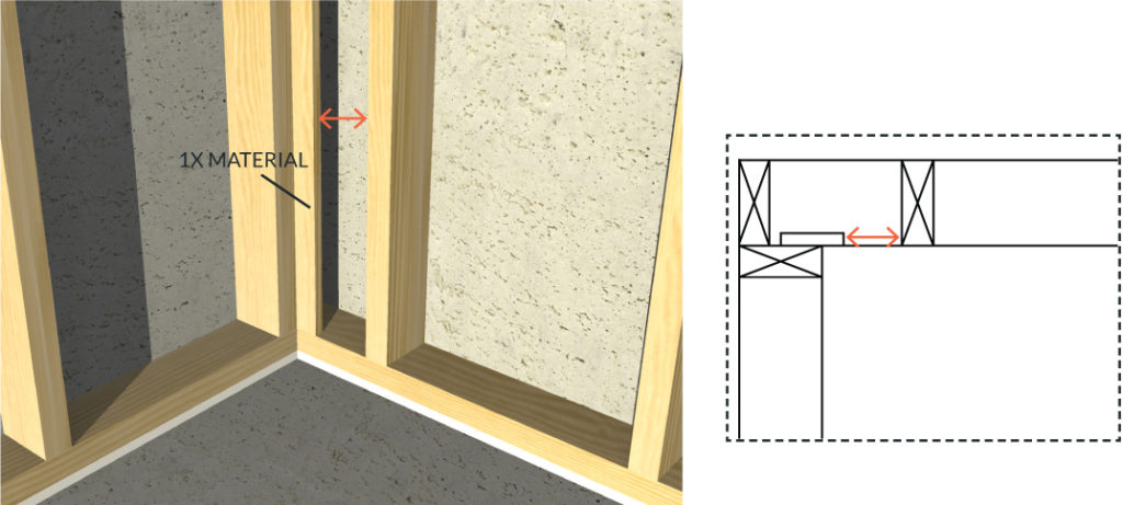
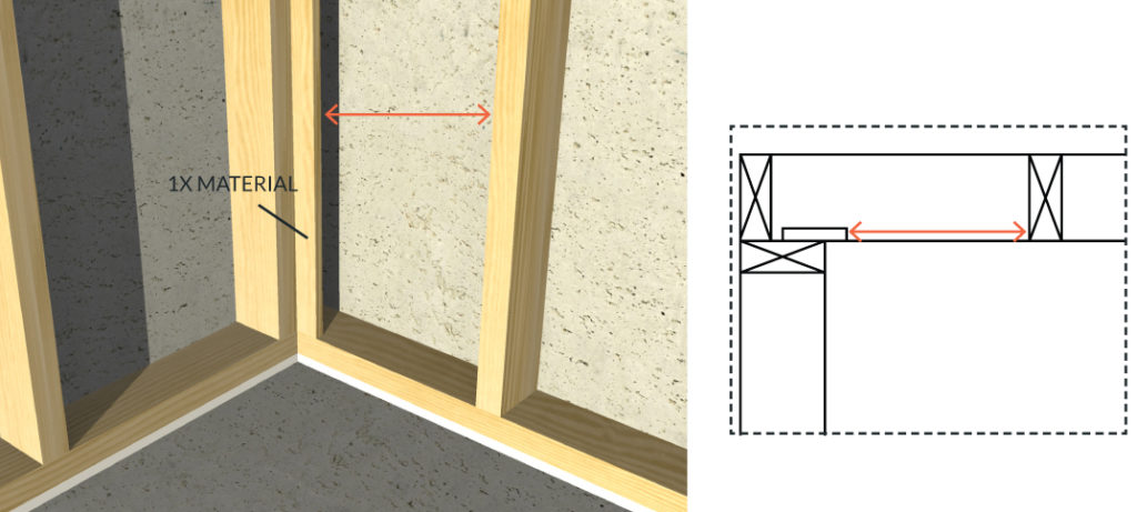
Framing Example at an Inside Corner:
Poor Spacing at Corner with Insufficient Clearance
Proper Spacing at Corner
Dense Pack Blown-In Cellulose
- At completion of project, insulation is to be enclosed on all 6 sides with rigid material to prevent wind washing/convection losses and settling. The specific quantity of material to be installed should always be calculated and confirmed by site superintendent. *See bag count
- Ensure good access to all areas for proper fill.
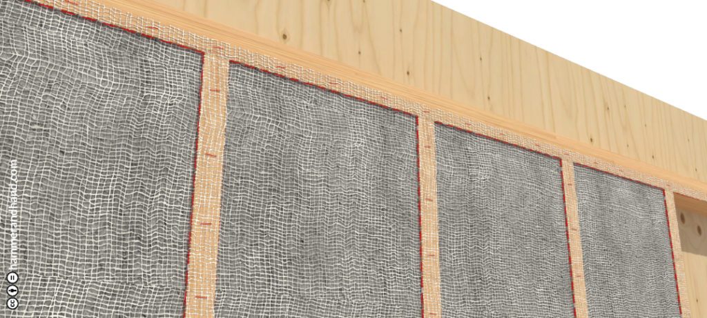
Netting
- Inset stapling at corner of stud to prevent intrusion of insulation to front of stud.
- Use dense pack specific netting material.
Netting is to be taut prior to fill. Check density after 10% of work is complete to confirm proper installation. At initial completion, review integrity of installation and remedy any under-filled areas.
Material density determined by manufacturer, should feel like solid felt. Keep dry with NO exposure to bulk water during construction.
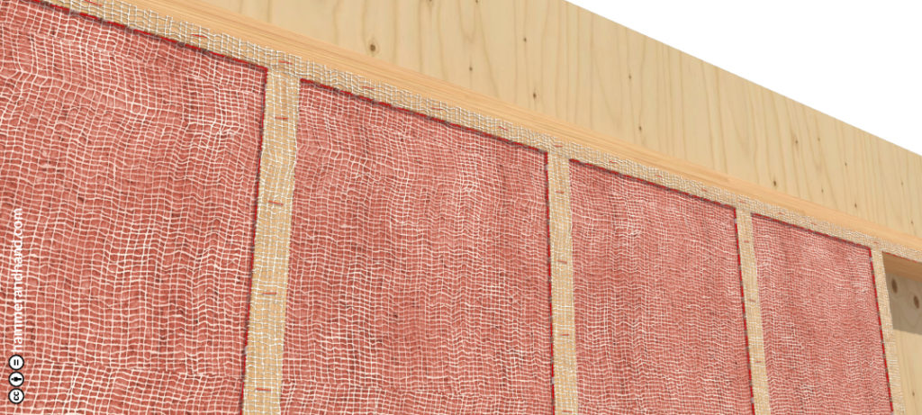
Fiberglass
- At completion of project, insulation is to be enclosed on all 6 sides with rigid material to prevent wind washing/convection losses and settling. The specific quantity of material to be installed should always be calculated and confirmed by site superintendent. *See bag count below.
- Ensure good access to all areas for proper fill.
Netting
- Inset stapling of netting at corner of stud to prevent intrusion of insulation to front of stud.
- Utilize netting per fiber glass manufacturer’s specifications.
Netting is to be taut prior to fill. Check density after 10% of work is complete to confirm proper installation. At initial completion, review integrity of installation and communicate any under-filled areas to insulation contractor.
Check building specifications for desired density. Keep dry during construction.
1. ‘Dense-Pack’ feels like a firm mattress. See manufacturer’s documentation for lbs/ft3 specifications.
2. ‘Standard Fill’ feels like a firm pillow. See manufacturer’s documentation for lbs/ft3 specifications.
* Bag Count Example:
435 SF of 2 x 6 wall
Framing factor of 18% (area taken up by wall framing)
(435 ft2 x 5.5/12 ft) x (100% – 18%)
(435 ft2 x .458 ft) x .82
199.375 ft3 x .82 = 163.5 ft3
Example: Fiberglass might be 1.8 lbs/ft3.
The 435 ft2 area needs 294.3 lbs of material.
Bags are 28 lbs/each, this wall needs 10.5 bags of material.
Attic Insulation
Loose Fill in Attics
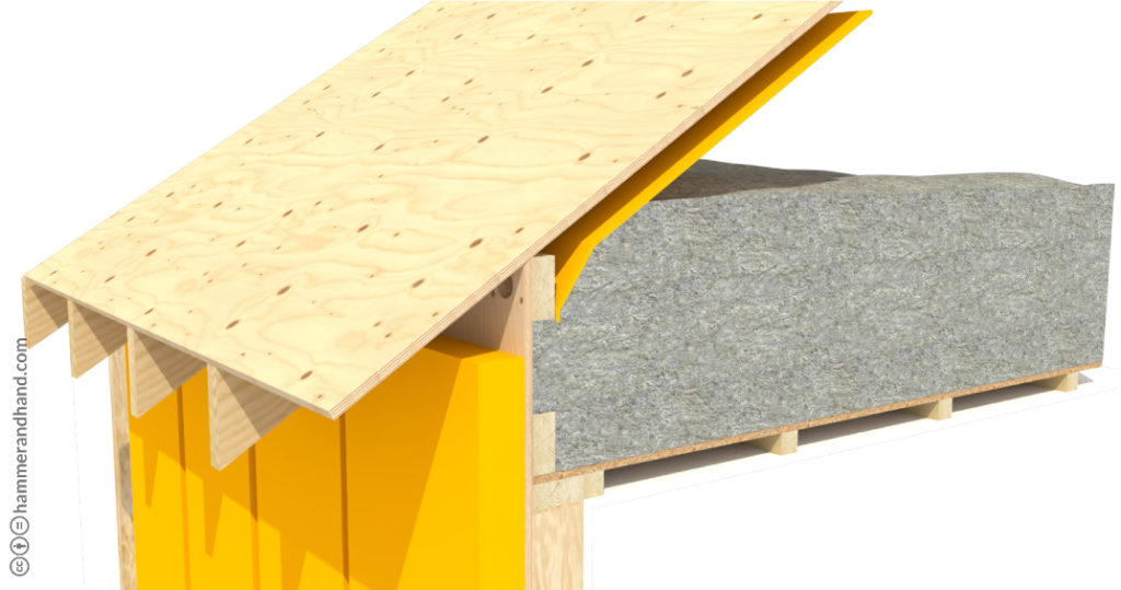
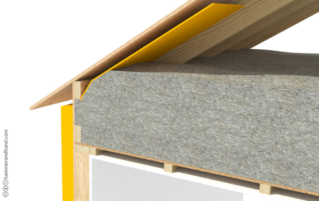
- Protect from wind-washing at perimeter, especially where close to roof venting.
- Roof baffles for soffit venting to terminate no less than 12 inches above cellulose to prevent wind from displacing material.
- Baffles between rafters to be continuous from rafter to rafter (do not use baffles which are fastened to roof sheathing). Must fill full width of cavity.
- Maximum slope of ceiling below loose fill: 5/12.
- Do not use blown-fiberglass due to light density/wind washing.
- Insulation depth markers to be installed per manufacturer’s specification.
- Where vertical walls are encountered in attic spaces (this condition occurs where ceiling heights change) install rigid material on attic side of framing and insulate from interior so area can be readily inspected post-installation of insulation material.
Attic Hatch
- Ensure proper clearance is present from ceiling to bottom of rafters to allow for access, post-installation of insulation; if current location does not allow for needed clearance, relocate hatch.
- Construct “dam” of plywood or other durable rigid panel (cardboard is not sufficient) to a height of final insulation depth plus 2.” Minimum height above dam to be 30” to allow for access to attic. Minimum rough framed opening of hatch per code to be 22” x 30.”
- Insulate hatch area with rigid insulation to the minimum R-value of general attic area. Allowable gap at perimeter of insulation panel to be a maximum of 1/4” per side. Hatch to be integrated into air barrier necessary to maintain airtightness.